Architectural Event Processing Model
An architectural event is a synchronous or asynchronous condition delivered through the common event-entry mechanism. Synchronous exceptions are faults or traps. Asynchronous events are maskable interrupts or NMIs. Fault and trap are the two exception subtypes. SYSCALL produces the explicit synchronous SYSTEM_CALL exception (event code 0x00000003) and uses this same mechanism.
Every event transfers to the exact program counter in EPC after loading ECS and EDS. Hardware supplies an event code and either a user-bank payload or a full supervisor frame whose layout is fixed by the event source. Software begins at one common entry point and dispatches by the event code.
Related normative instruction entries are BKPT, SYSCALL, ERET, and RESET.
Event Code and Sources
Every delivered event carries a 32-bit code. The high byte is the event class and the low 24 bits are an ID in that class's namespace.

Architectural Event Code
Architectural Event Classes
| Value | Class | Name | Selector policy |
|---|---|---|---|
0x00 |
EXCEPTION |
Synchronous Exception | fixed 24-bit selector |
0x01 |
INTERRUPT |
Maskable Interrupt | identity 24-bit selector |
0x02 |
NMI |
Non-Maskable Interrupt | source 24-bit selector |
Class values not listed above are reserved. Fixed selectors are assigned by this specification; platform and source selectors are supplied by the corresponding event source.
The following fixed event codes are assigned by this specification. Each row answers only which symbolic event is assigned to a fixed code; the event’s behavior, frame, and payload are defined by the topic that owns that behavior.
Fixed Architectural Event-Code Assignments
Unassigned base-profile exception IDs are reserved. Interrupt identities do not share a namespace with exception IDs. Interrupt-controller routing, native-ID mapping, ownership, trigger mode, and any external acknowledgement or end-of-interrupt protocol belong to the platform ABI. A valid posted identity is recorded in the target logical processor’s architectural interrupt file; the delivered event code has class 0x01 and that identity in its low 24 bits.
Deadline-timer expiry uses the same posting operation with the identity supplied by TARM. It does not define a fixed timer identity or a separate interrupt-source catalog member.
A restartable fault saves the faulting instruction or its architecturally defined restart point. A trap saves the following instruction. An interrupt or NMI saves the next instruction that would otherwise execute. A faulting repeat iteration rolls back without decrementing its counter, then saves the repeat-prefix address. After a successful repeat iteration, the counter decrement commits before an event may be admitted between iterations; that event also saves the repeat-prefix address. Event entry clears hidden repeat state, and ERET executes the saved prefix normally without restoring repeat continuation.
Event Priority and Debug Stops
When events compete at one architectural boundary, delivery failure is selected before machine check. Instruction and operand validation, address formation, translation, permission, alignment, and other higher-priority synchronous faults precede debug-trigger evaluation. A pre-effect execution breakpoint or memory watchpoint is selected before any result of the stopped instruction and before NMI or a maskable interrupt at the same boundary. After successful completion, an explicit EXPLICIT_BREAKPOINT is selected before SINGLE_STEP; NMI and maskable interrupts follow automatic debug events. An asynchronous event that is not selected remains pending.
A trace unit is one ordinary committed instruction or one committed REP or REPcc body iteration. Completion of a zero-count REP or REPcc is also one trace unit. STATUS.TF is sampled at the start of the unit. If sampled STATUS.TF is one and sampled STATUS.RF is zero, successful completion commits the unit and then delivers SINGLE_STEP with the following trace-unit boundary as its saved PC.
The TRACE marker instruction is an ordinary instruction for this rule. Its marker is recorded before a pending SINGLE_STEP is delivered. The Tracing Terms section distinguishes the marker instruction, trace unit, and SINGLE_STEP event.
STATUS.RF suppresses SINGLE_STEP and every automatic execution or memory trigger for one trace unit. It does not suppress EXPLICIT_BREAKPOINT or the TRACE marker. If sampled STATUS.RF is one, successful trace-unit completion clears STATUS.RF. A fault or asynchronous event before successful completion preserves it. Event entry saves the old STATUS image and clears live STATUS.TF and STATUS.RF. Entry for a pre-effect hardware-trigger event first sets STATUS.RF in the saved return STATUS image, allowing a normal return to retry the instruction once without an immediate retrigger. A handler may clear that saved STATUS.RF bit to request deliberate retriggering.
Entry Admission and Event Depth
The event-entry state is usable only while ECR.V is set. A maskable interrupt is admitted only when ECR.V, STATUS.IE, and the depth limit all permit it: the current event depth must be less than ECR.MAX_EDEPTH. The interrupt file additionally requires a pending and enabled identity that passes ITHRESH; ITOP chooses the numerically lowest such identity. Otherwise the identity remains pending in the interrupt file. A synchronous exception that requires delivery while ECR.V is clear cannot be deferred and enters SHUTDOWN. An NMI observed while ECR.V is clear sets the hardware-managed ECR.NMI_P latch and is not admitted. After ECR.V becomes one, hardware admits that pending NMI before the next instruction boundary when STATUS.NI is clear. While STATUS.NI remains set, the NMI remains pending. Multiple NMI observations coalesce in ECR.NMI_P.
Event depth is zero outside event handling. A successful entry saves STATUS in the selected return context and increments STATUS.EDEPTH. ECR.MAX_EDEPTH equal to zero prevents maskable interrupt admission; values 1 through 15 limit only maskable interrupts and do not suppress synchronous exceptions or NMI. Depth 15 is representable but terminal: any further event requirement enters SHUTDOWN. At depth 14 or less, a delivery failure can still create an EVENT_DELIVERY_FAILURE family frame; at depth 15 there is no representable child frame.
Supervisor Event Stacks and Nesting
The configured supervisor stack pairs select only the first user-origin entry and delivery-failure recovery.
Supervisor Stack Roles
| Pair | Role | Use |
|---|---|---|
SSS:SSP |
system call | first user-origin SYSTEM_CALL |
ISS:ISP |
interrupt | first user-origin maskable interrupt |
FSS:FSP |
fault | first user-origin exception or NMI |
DSS:DSP |
recovery | EVENT_DELIVERY_FAILURE family event |
A first user-origin entry loads the applicable configured pair. Supervisor-origin and all nested entries retain the current SS:SP and push a full frame there; event class never promotes an active handler to another configured stack. Delivery failure uses DSS:DSP when the hidden current-DFA bit is clear. Failure with current DFA set enters shutdown.
For user-origin entry, hardware rounds only the event payload to 16 bytes and subtracts it from the configured top. BASIC events have zero payload and perform no stack access. For supervisor or nested entry, hardware subtracts the complete full-frame size from current SP. Each nonzero range is validated and stored atomically before the new SP commits; configured tops are never modified.
Events in the EVENT_DELIVERY_FAILURE family use DSS:DSP. Supervisor-origin and nested events retain the current SS:SP; ERET validates and restores the saved STATUS depth and origin chain.
WRCR to SSS, ISS, FSS, or DSS accepts a complete valid segment image. WRCR to SSP, ISP, FSP, or DSP accepts a complete 64-bit stack top aligned to 64 bytes. A successful write atomically replaces the selected register; event entry and return do not modify the configured segment or top.
Event Entry State
Before making an event visible, hardware validates EPC, ECS, EDS, the selected stack state, and the complete frame storage range. It then stores the frame, loads the entry segments and PC, sets STATUS.PM and STATUS.EA, and clears STATUS.IE, STATUS.TF, and STATUS.RF as one architectural commit. R0 through R15 and GS0 through GS5 are unchanged; the common entry code preserves whatever its software ABI requires.
WRCR to EPC accepts a complete 64-bit entry address and requires it to be 16-byte aligned, canonical, and executable under ECS. WRCR to ECS or EDS accepts a complete valid segment image. A successful write atomically replaces the selected register.
NMI entry additionally sets STATUS.NI. Other event classes preserve STATUS.NI. A further NMI observed while STATUS.NI is set is recorded by setting ECR.NMI_P. ECR.NMI_P is hardware managed, so WRCR ignores the supplied value for that bit. When entry of an NMI admitted from ECR.NMI_P commits, hardware clears ECR.NMI_P as part of the same architectural transition. A newly observed NMI may set the latch again. An entry failure does not clear the latch before committing the specified delivery-failure result. When ERET successfully restores STATUS.NI to zero, a pending NMI is delivered before the next instruction boundary.
WRCR to ECR takes ECR.MAX_EDEPTH and ECR.V from the source image and preserves the hardware-managed ECR.NMI_P value. A transition that changes ECR.V from zero to one validates EPC, ECS, EDS, and every configured event-stack segment and top before atomically replacing the writable ECR image.
When maskable-interrupt entry commits, hardware clears exactly the delivered identity’s pending bit in the same architectural transition. Entry validation, target probing, frame-address, or frame-store failure preserves that bit; a later posting of the same identity continues to coalesce while it remains pending.
STATUS.EA, STATUS.EDEPTH, STATUS.UO, and STATUS.PM are hardware-managed transition state. WRSTATUS must preserve their current values. An attempted change raises RESERVED_CONTROL_BITS without modifying STATUS. WRSTATUS may change STATUS.IE, STATUS.NI, STATUS.TF, and STATUS.RF. Clearing STATUS.NI while ECR.NMI_P is one admits the pending NMI at the next instruction boundary. ERET classifies direct U-bank, outer U-bank, and stacked returns before any stack access; an invalid combination raises INVALID_CONTROL_TRANSITION without consuming either return source.
Architectural Event Frame
Every event frame begins with exactly eight 64-bit slots. EVENT_INFO contains EVENT_INFO.EVENT_CODE in bits 31 through 0; its upper half is zero. FRAME_CONTROL contains only frame shape, saved nesting state, saved FRAME_CONTROL.FLAGS, and saved FRAME_CONTROL.STATUS. Event classification is carried exclusively by EVENT_INFO.
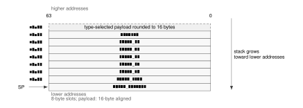
Architectural Event Frame
Architectural Event Frame Fields
| Offset | Slot | Meaning |
|---|---|---|
| +0x00 | FRAME_CONTROL |
frame shape, nesting metadata, saved FLAGS, and saved STATUS |
| +0x08 | EVENT_INFO |
EVENT_CODE in bits 31..0; bits 63..32 are zero |
| +0x10 | SAVED_PC |
saved program counter |
| +0x18 | SAVED_SP |
saved stack pointer |
| +0x20 | SAVED_CS |
saved code-segment image |
| +0x28 | SAVED_DS |
saved data-segment image |
| +0x30 | SAVED_SS |
saved stack-segment image |
| +0x38 | PADDING |
ignored by ERET; software may write any value |
| +0x40 | ERROR_CODE |
exception-specific error code; unassigned bits are zero |
| +0x48 | FAULT_EA |
numeric effective address before segment pre-translation |
| +0x50 | FAULT_LINEAR |
address after segment pre-translation |
| +0x58 | EVENT_AUX |
delivery-failure, machine-check, or bus-failure auxiliary information |

FRAME_CONTROL Format
In the diagram, D abbreviates FRAME_CONTROL.SAVED_DFA.
FRAME_CONTROL Fields
| Field | Bits | Meaning |
|---|---|---|
FRAME_SIZE |
0..7 | total allocated frame size in 8-byte units |
FRAME_TYPE |
8..11 | optional payload layout code; it does not classify the event |
SAVED_DFA |
12 | prior hidden delivery-failure-active state |
| reserved | 13..31 | reserved; must be zero |
FLAGS |
32..35 | saved FLAGS image |
STATUS |
36..51 | saved STATUS image, including STATUS.EDEPTH and STATUS.UO |
| reserved | 52..63 | reserved; must be zero |
ERET first validates the frame shape and nesting metadata. BASIC requires FRAME_CONTROL.FRAME_SIZE=8, ERROR requires 10, and PAGE and AUXILIARY require 12. It requires saved STATUS.PM=1, saved STATUS.EDEPTH plus one to equal the current depth, and saved STATUS.UO to match the active outer-origin chain.
Only after those checks does ERET validate the saved control state, segment images, SP, and PC. On success it restores FRAME_CONTROL.FLAGS, FRAME_CONTROL.STATUS, CS, DS, SS, SP, PC, and current DFA as one commit. It ignores the fixed-header PADDING slot at +0x38 and restores no hidden repeat state. EVENT_INFO and the event-specific payload remain available to software.
Event Payloads
Payload starts at offset +0x40. Hardware allocates only the defined payload prefix, rounds it up to a 16-byte boundary, and zeros the padding. The frame-size unit remains one 8-byte slot.
Architectural Event Frame Types and Sizes
| Code | Type | Payload | Allocated | Total | Size | Last slot |
|---|---|---|---|---|---|---|
| 0x0 | BASIC | 0 | 0 | 64 | 8 | none |
| 0x1 | ERROR | 8 | 16 | 80 | 10 | ERROR_CODE |
| 0x2 | PAGE | 24 | 32 | 96 | 12 | FAULT_LINEAR |
| 0x3 | AUXILIARY | 32 | 32 | 96 | 12 | EVENT_AUX |
The delivered leaf event determines the frame type. ERROR_CODE is defined separately by each event that uses it and has zero in every unassigned bit. PAGE frames extend that slot with effective-address and linear-address context. AUXILIARY includes all four named slots and permits EVENT_AUX to describe delivery-failure, machine-check, or bus-failure state.
A misaligned atomic memory operand raises ATOMIC_ALIGNMENT_FAULT and uses the PAGE frame. FAULT_EA identifies the misaligned effective-address operand and FAULT_LINEAR contains its segment-pretranslated starting address. The fault is reported before the atomic instruction performs a memory read, memory write, or architectural result update.
Execution-breakpoint and memory-watchpoint payloads are defined in the debug-event payload format. Their pre-effect timing is part of the Architectural Debug Triggers contract.
Address-Context Payload
Events in the ADDRESS_TRANSLATION and PHYSICAL_ACCESS families use the PAGE frame. The leaf event code identifies the failure; ERROR_CODE carries only the access context common to those events.

PAGE Event ERROR_CODE Format
SZ, L, E, OP, LVL, and AC denote PAGE_ERROR_CODE.ACCESS_SIZE, PAGE_ERROR_CODE.FAULT_LINEAR_VALID, PAGE_ERROR_CODE.FAULT_EA_VALID, PAGE_ERROR_CODE.OPERAND, PAGE_ERROR_CODE.WALK_LEVEL, and PAGE_ERROR_CODE.ACCESS; A and U denote PAGE_ERROR_CODE.ATOMIC and PAGE_ERROR_CODE.USER_DOMAIN.
PAGE Event ERROR_CODE Fields
| Bits | Field | Meaning |
|---|---|---|
| 7..0 | reserved | zero; failure identity is carried by EVENT_INFO.EVENT_CODE |
| 9..8 | ACCESS |
0 none, 1 read, 2 write, 3 execute |
| 10 | USER_DOMAIN |
access selected the user-domain permission path |
| 11 | ATOMIC |
access was an atomic read-modify-write |
| 14..12 | WALK_LEVEL |
0 before or without a walk; 1 through 4 identify the PTE level |
| 15 | reserved | zero |
| 23..16 | OPERAND |
zero-based explicit operand ordinal; 0xff for implicit fetch or stack access |
| 24 | FAULT_EA_VALID |
FAULT_EA was produced |
| 25 | FAULT_LINEAR_VALID |
FAULT_LINEAR was produced |
| 26 | reserved | zero |
| 29..27 | ACCESS_SIZE |
0 unavailable or inapplicable; 1 B; 2 W; 3 L; 4 Q |
| 63..30 | reserved | zero |
Saved STATUS.PM records the originating privilege. PAGE_ERROR_CODE.USER_DOMAIN distinguishes the ordinary user permission path from the checked user-access path used by supervisor instructions such as MOVUC, MOVCU, and MOVUU. An atomic read-modify-write reports PAGE_ERROR_CODE.ACCESS=write. Events detected during a page-table walk report the applicable level; events detected before a walk and every event in the PHYSICAL_ACCESS family report level zero.
PAGE_ERROR_CODE.ACCESS_SIZE records the architectural transfer width when one of the B, W, L, or Q widths applies. It is zero when no such width is available or applicable. FAULT_EA is the numeric effective address before segment pre-translation. FAULT_LINEAR is the result after segment pre-translation. A value not produced is zero and has its corresponding validity bit clear.
Other Exception Payloads
Integer-divide, instruction-validation, control-state, and privilege failures are represented by distinct leaf events. Their event code identifies the precise condition, so events without a defined payload use BASIC frames and do not repeat a cause number in ERROR_CODE.
The bounds instructions report comparison failure through FLAGS.V. Segment bounds failures raise SEGMENT_BOUNDS_VIOLATION. Debug-event payloads are defined separately for their distinct event identities.
Debug Event Payloads
SINGLE_STEP and EXPLICIT_BREAKPOINT use BASIC frames and carry no address payload. EXECUTION_BREAKPOINT uses an ERROR frame; ERROR_CODE bits 15 through 0 contain the TRIGGER_SLOT number and all other bits are zero. Its saved PC is the matched address.
The three memory-watchpoint events use PAGE frames. FAULT_EA contains the matched pre-segment effective address and FAULT_LINEAR contains its segment-pretranslated linear address. ERROR_CODE has the following event-specific format.

Memory-Watchpoint ERROR_CODE Format
L, M, and U abbreviate MEMORY_WATCHPOINT_ERROR_CODE.LINEAR_VALID, MEMORY_WATCHPOINT_ERROR_CODE.MMIO, and MEMORY_WATCHPOINT_ERROR_CODE.USER_DOMAIN.
Memory-Watchpoint ERROR_CODE Fields
| Bits | Field | Meaning |
|---|---|---|
| 15..0 | TRIGGER_SLOT |
zero-based winning trigger-slot number |
| 23..16 | OPERAND |
zero-based explicit memory-operand ordinal; 0xff for an implicit data access |
| 39..24 | ACCESS_SIZE |
number of bytes in the matched architectural access |
| 40 | USER_DOMAIN |
access selected the user permission domain |
| 41 | MMIO |
translated access was classified as MMIO rather than Normal |
| 42 | LINEAR_VALID |
FAULT_LINEAR contains the segment-pretranslated address |
| 63..43 | reserved | zero |
Floating-Point Exception Payload
The FLOATING_POINT_EXCEPTION event uses an ERROR frame because one operation may raise several enabled floating-point conditions together. ERROR_CODE[4:0] is a bitmap: bits 4 through 0 are NV, DZ, OF, UF, and NX; bits 63 through 5 are zero.

FLOATING_POINT_EXCEPTION ERROR_CODE Format
I, Z, O, U, and X abbreviate NV, DZ, OF, UF, and NX.
Control-Flow Integrity Violation
The CONTROL_FLOW_INTEGRITY_VIOLATION event uses an error frame. ERROR_CODE value 1 identifies an indirect-landing failure and value 2 identifies return-authentication failure. The payload does not expose a candidate continuation, supplied or expected PA, or key-derived value. A failed check commits no stack, resident-state, or control-transfer change.
Auxiliary Payloads
For an AUXILIARY frame, ERROR_CODE bit 26 is the applicable DELIVERY_FAILURE_ERROR_CODE.EVENT_AUX_VALID, MACHINE_CHECK_ERROR_CODE.EVENT_AUX_VALID, or BUS_FAILURE_ERROR_CODE.EVENT_AUX_VALID field. Bits 24 and 25 are the corresponding address-validity fields when the event can supply those addresses. Every unassigned bit is zero, and an auxiliary or address value not produced is zero with its validity bit clear.
Delivery-failure stages are represented by distinct leaf events. Their EVENT_INFO.EVENT_CODE identifies the failed stage; the EVENT_AUX payload records the event whose delivery failed.
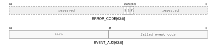
Delivery-Failure Auxiliary Format
E, L, and F are EVENT_AUX_VALID, FAULT_LINEAR_VALID, and FAULT_EA_VALID.
When DELIVERY_FAILURE_ERROR_CODE.EVENT_AUX_VALID is one, EVENT_AUX[31:0] contains the event code whose delivery failed and bits 63..32 are zero. A EVENT_FRAME_ADDRESS_FAILURE or EVENT_FRAME_STORE_FAILURE supplies FAULT_EA and FAULT_LINEAR when those values were produced.
For MACHINE_CHECK, the error code has this layout:

MACHINE_CHECK ERROR_CODE Format
E, L, and F are MACHINE_CHECK_ERROR_CODE.EVENT_AUX_VALID, MACHINE_CHECK_ERROR_CODE.FAULT_LINEAR_VALID, and MACHINE_CHECK_ERROR_CODE.FAULT_EA_VALID; P, R, SV, and SRC denote MACHINE_CHECK_ERROR_CODE.PRECISE, MACHINE_CHECK_ERROR_CODE.RETRY_SAFE, MACHINE_CHECK_ERROR_CODE.SEVERITY, and MACHINE_CHECK_ERROR_CODE.SOURCE.
MACHINE_CHECK ERROR_CODE Fields
| Bits | Field | Meaning |
|---|---|---|
| 7..0 | SOURCE |
0 unknown; 1 core; 2 cache; 3 translation; 4 memory; 5 interconnect |
| 9..8 | SEVERITY |
0 corrected; 1 recoverable; 2 fatal; 3 reserved |
| 10 | PRECISE |
saved PC identifies the responsible instruction and saved architectural state precedes it |
| 11 | RETRY_SAFE |
retry at that precise boundary cannot duplicate an external effect |
| 23..12 | reserved | zero |
| 24 | FAULT_EA_VALID |
FAULT_EA was produced |
| 25 | FAULT_LINEAR_VALID |
FAULT_LINEAR was produced |
| 26 | EVENT_AUX_VALID |
EVENT_AUX was produced |
| 63..27 | reserved | zero |
When MACHINE_CHECK_ERROR_CODE.EVENT_AUX_VALID is one, EVENT_AUX contains an implementation-defined syndrome. Associated effective and linear addresses are supplied when available.
MACHINE_CHECK_ERROR_CODE.RETRY_SAFE=1 requires MACHINE_CHECK_ERROR_CODE.PRECISE=1. The valid MACHINE_CHECK_ERROR_CODE.SEVERITY and continuation combinations are:
MACHINE_CHECK Valid Continuation Combinations
MACHINE_CHECK_ERROR_CODE.SEVERITY |
MACHINE_CHECK_ERROR_CODE.PRECISE |
MACHINE_CHECK_ERROR_CODE.RETRY_SAFE |
Saved PC and continuation meaning |
|---|---|---|---|
| corrected | 0 | 0 | Trap; saved PC is the instruction following the corrected operation. |
| recoverable | 0 | 0 | Saved PC is the next instruction that would execute at the delivery boundary; saved architectural state is the state at that boundary. It does not identify the responsible operation. |
| recoverable | 1 | 0 | Saved PC identifies the responsible instruction and architectural state precedes it; retry may duplicate an external effect. |
| recoverable | 1 | 1 | Saved PC identifies the responsible instruction and architectural state precedes it; retry cannot duplicate an external effect. |
| fatal | 0 | 0 | Saved PC is the next instruction at the delivery boundary and is diagnostic only. |
| fatal | 1 | 0 | Saved PC identifies the responsible instruction and pre-instruction architectural state for diagnosis only. |
All other combinations are invalid and are not generated. In particular, corrected machine checks never set either bit, MACHINE_CHECK_ERROR_CODE.PRECISE=0, MACHINE_CHECK_ERROR_CODE.RETRY_SAFE=1 is invalid for every severity, fatal machine checks never set MACHINE_CHECK_ERROR_CODE.RETRY_SAFE, and MACHINE_CHECK_ERROR_CODE.SEVERITY 3 is reserved. A fatal event provides no reliable continuation even when its diagnostic state is precise.
For an event in the BUS_FAILURE family, the error code has this layout:

BUS_FAILURE ERROR_CODE Format
E, L, and F are BUS_FAILURE_ERROR_CODE.EVENT_AUX_VALID, BUS_FAILURE_ERROR_CODE.FAULT_LINEAR_VALID, and BUS_FAILURE_ERROR_CODE.FAULT_EA_VALID; SZ, OP, LVL, and AC denote BUS_FAILURE_ERROR_CODE.ACCESS_SIZE, BUS_FAILURE_ERROR_CODE.OPERAND, BUS_FAILURE_ERROR_CODE.WALK_LEVEL, and BUS_FAILURE_ERROR_CODE.ACCESS; A, U, and R denote BUS_FAILURE_ERROR_CODE.ATOMIC, BUS_FAILURE_ERROR_CODE.USER_DOMAIN, and BUS_FAILURE_ERROR_CODE.RETRY_SAFE.
BUS_FAILURE ERROR_CODE Fields
| Bits | Field | Meaning |
|---|---|---|
| 7..0 | reserved | zero; failure identity is carried by EVENT_INFO.EVENT_CODE |
| 9..8 | ACCESS |
0 none, 1 read, 2 write, 3 execute |
| 10 | USER_DOMAIN |
access selected the user-domain permission path |
| 11 | ATOMIC |
access was an atomic read-modify-write |
| 14..12 | WALK_LEVEL |
0 outside a walk; 1 through 4 identify the PTE level |
| 15 | reserved | zero |
| 23..16 | OPERAND |
zero-based explicit operand ordinal; 0xff for implicit fetch or stack access |
| 24 | FAULT_EA_VALID |
FAULT_EA was produced |
| 25 | FAULT_LINEAR_VALID |
FAULT_LINEAR was produced |
| 26 | EVENT_AUX_VALID |
EVENT_AUX was produced |
| 29..27 | ACCESS_SIZE |
0 unavailable or inapplicable; 1 B; 2 W; 3 L; 4 Q |
| 30 | RETRY_SAFE |
retry cannot duplicate an external effect |
| 63..31 | reserved | zero |
A bus error during a page walk reports the level whose PTE access failed. When BUS_FAILURE_ERROR_CODE.EVENT_AUX_VALID is one, EVENT_AUX contains the final byte address available for the failed access.
Machine-Check and Bus-Error Continuation
A corrected MACHINE_CHECK is a trap, has both MACHINE_CHECK_ERROR_CODE.PRECISE and MACHINE_CHECK_ERROR_CODE.RETRY_SAFE clear, and saves the following instruction. A recoverable machine check uses the valid combinations in the auxiliary-payload table. When MACHINE_CHECK_ERROR_CODE.PRECISE is one, the saved PC identifies the responsible instruction boundary and logical-processor architectural state is the state from before that instruction. When it is zero, the saved PC is the next instruction that would execute at the delivery boundary and architectural state corresponds to that boundary; neither identifies the responsible operation. MACHINE_CHECK_ERROR_CODE.RETRY_SAFE may be one only with MACHINE_CHECK_ERROR_CODE.PRECISE=1 and additionally guarantees that returning to the responsible boundary cannot duplicate an external effect. A fatal machine check always clears MACHINE_CHECK_ERROR_CODE.RETRY_SAFE; MACHINE_CHECK_ERROR_CODE.PRECISE then describes diagnostic location quality and never guarantees reliable continuation.
Every event in the BUS_FAILURE family is a synchronous precise fault. Logical-processor architectural state remains uncommitted and the saved PC identifies the responsible instruction boundary. Its separate BUS_FAILURE_ERROR_CODE.RETRY_SAFE bit states whether an external effect might already have occurred. Page-walk and ordinary memory bus errors are retry-safe.
Software interprets the machine-check continuation fields before choosing a return or recovery action.
Delivery Failure and Shutdown
Failure to validate the common entry context, establish the selected stack, or store a complete event frame is delivered as the corresponding EVENT_DELIVERY_FAILURE leaf event on DSS:DSP. Failure while such an event is already being delivered enters SHUTDOWN. SHUTDOWN retires no further instructions and can be exited only by a platform reset. The frame save and all architectural entry state remain atomic, so a failed attempt never exposes a partially stored frame or partially changed execution context.
Event Reset and Context State
Warm RESET is supervisor-only and affects only the executing logical processor. Before the reset-state transition commits, all earlier memory effects and pending write-combining stores from that logical processor complete. Other logical processors are unchanged.
The transition clears R0 through R15, SP, and FLAGS. It sets PC to BOOTPC and sets STATUS.PM to one while clearing every other STATUS bit. It clears CS, DS, SS, GS0 through GS5, PTCR, ASCR, ECR, EPC, ECS, EDS, the complete user context bank (UPC, USP, UCS, UDS, USS, UCTL, and UINFO), and the configured event stacks and segments (SSS, SSP, ISS, ISP, FSS, FSP, DSS, and DSP). It also clears PMC, CYCLE, INSTRET, and PTWALK. Clearing ECR clears its hardware-managed ECR.NMI_P as part of the same transition. It clears all interrupt-file pending and enable bits, ITHRESH, and ISEL while preserving the implementation capability reported by ICAP.MAX_ID. It resets DTRSEL and disables every architectural debug-trigger slot. It disarms the deadline timer while preserving the invariant timebase value and frequency. Timer reset does not independently clear interrupt-file state.
Warm RESET invalidates hidden repeat state, the load reservation, local translation and page-walk caches, decoded instruction state, and local prefetch state. It clears the hidden current DFA. Coherent data- and instruction-cache contents remain coherent. Instruction-fetch synchronization completes before the first instruction at BOOTPC is fetched, at which point the processor is running at BOOTPC.
BOOTPC and BOOTCFG are preserved by warm RESET. Cold reset initializes them from platform-supplied values before applying the same processor-state image to each logical processor selected by the platform reset event. Software initializes entry segments, exact entry PCs, and configured stack tops before setting ECR.V or entering user mode. WRCR atomically replaces the complete 64-bit BOOTPC or opaque BOOTCFG image without transformation. A later warm RESET uses BOOTPC as its exact resumed PC and preserves both images.
ECR, entry and stack registers, STATUS.EDEPTH/STATUS.UO, hidden current DFA, the interrupt file, the debug-trigger array, and the user context bank are per-logical-processor state. Event entry preserves the debug-trigger array. System software includes the applicable processor state listed above when switching supervisor contexts and manages the debug-trigger array separately. Payloads and full event frames reside in byte-addressed normal memory owned by the interrupted context.