Programming Model
Register Model
The general-purpose register set contains sixteen 64-bit registers, R0 through R15. Instruction encodings use these registers for integer values, addresses, counters, selectors, and temporary data.
SP and PC are special architectural registers outside the four-bit Rn namespace. SP-relative memory forms use SS by default; PC-relative memory forms use CS by default.
CS, DS, SS, and GS0 through GS5 are 64-bit architectural segment registers. Segment-qualified EA forms select them explicitly, while SP and PC forms omit the segment field because their segment association is fixed.
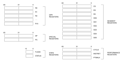
Base Register Model
FLAGS and STATUS Registers
FLAGS and STATUS are accessed through dedicated read/write instructions.

FLAGS Register Format
FLAGS Fields
| Field | Bits | Meaning |
|---|---|---|
| reserved | 15..4 |
reads as zero and must be zero when written |
Z |
3 |
result value is zero |
N |
2 |
most significant result bit at the operand size |
C |
1 |
unsigned carry out for addition or unsigned borrow for subtraction |
V |
0 |
signed overflow or an explicitly reported exceptional condition |
RDFLAGS and WRFLAGS are unprivileged. RDFLAGS reads and zero-extends the 16-bit image; WRFLAGS writes the low 16 bits and requires every reserved bit to be zero. Instruction-specific flag production and conditional use are defined in Flags and Condition Codes.

STATUS Register Format
In the diagram, U, DEPTH, I, P, R, T, N, and E abbreviate STATUS.UO, STATUS.EDEPTH, STATUS.IE, STATUS.PM, STATUS.RF, STATUS.TF, STATUS.NI, and STATUS.EA.
STATUS Fields
| Field | Bits | Meaning |
|---|---|---|
| reserved | 15..11 |
reads as zero and must be zero when written |
UO |
10 |
outer active event originated in user mode |
EDEPTH |
9..6 |
current architectural event depth |
IE |
5 |
permits maskable-interrupt admission when the other admission conditions hold |
PM |
4 |
selects user mode when zero and supervisor mode when one |
RF |
3 |
one-shot suppression of automatic single-step, execution-breakpoint, and memory-watchpoint stops |
TF |
2 |
requests post-success SINGLE_STEP for a trace unit when STATUS.RF is clear |
NI |
1 |
inhibits NMI admission while preserving the NMI pending |
EA |
0 |
hardware-managed architectural event-active state |
In user mode, STATUS.PM, STATUS.EA, STATUS.EDEPTH, and STATUS.UO are always observed as zero.
RDSTATUS is unprivileged; WRSTATUS is supervisor-only. WRSTATUS atomically updates STATUS.IE, STATUS.NI, STATUS.TF, and STATUS.RF; reserved bits must be zero, and supplied STATUS.PM, STATUS.EA, STATUS.EDEPTH, and STATUS.UO must equal their current values. Privilege transitions are defined in the Privileged Execution Model; event admission, tracing, and event-active transitions are defined in the Architectural Event Processing Model.
Floating-Point Register Model
The floating-point extension exposes F0 through F15 as 64-bit registers when the floating-point instruction group is implemented.
H-valued conversion operands occupy bits 15..0, S values occupy bits 31..0, and D values occupy all 64 bits. Writing H or S writes zero to the unused upper bits. The presence of an H conversion value in Fn does not enable scalar H arithmetic.
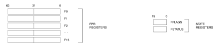
FP Register Model
FFLAGS and FSTATUS Registers
FFLAGS holds accrued IEEE-754 floating-point exception flags. FSTATUS holds the matching exception-condition enables, rounding mode, and optional NaN and subnormal handling modes. Both registers are present only with the floating-point extension and reset to zero.

FFLAGS Register Format

FSTATUS Register Format
In the diagrams, I, Z, O, U, and X denote the NV, DZ, OF, UF, and NX flag or enable bits. In FSTATUS, D, A, F, and R denote DN, DAZ, FTZ, and RM.
FFLAGS Fields
| Field | Bits | Meaning |
|---|---|---|
| reserved | 15..5 |
reads as zero and must be zero when written |
NV..NX |
4..0 |
accrued invalid, divide-by-zero, overflow, underflow, and inexact flags |
FSTATUS Fields
| Field | Bits | Meaning |
|---|---|---|
| reserved | 15..10 |
reads as zero and must be zero when written |
DN |
9 |
produce the architectural default NaN |
DAZ |
8 |
treat subnormal inputs as signed zero |
FTZ |
7 |
flush tiny results to signed zero |
RM |
6..5 |
0 nearest-even; 1 toward zero; 2 toward negative; 3 toward positive |
NV_EN..NX_EN |
4..0 |
floating-point exception-condition enables corresponding to FFLAGS.NV through FFLAGS.NX |
Vector Register Model
The scalable-vector extension provides 32 vector registers, V0 through V31, and 16 predicate registers, P0 through P15. A vector register contains VLEN bits. VLEN is an implementation-selected power of two from 128 through 2048 bits and remains stable until reset. A predicate register contains one bit for each byte of a vector register; its packed image therefore occupies VLEN/64 bytes. Reset clears every vector and predicate bit.
The VECTOR discovery predicate and the VECTOR_PARAMETERS CPUID leaf report the extension and VLEN. Integer and raw-bit vector forms require VECTOR. Floating-point vector operations are provided by the separate VECTORFP extension.
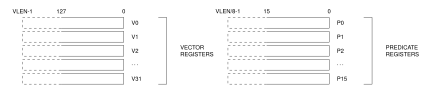
VECTOR Register Model
Segment Registers

Segment Register Format
Segment Register Fields
The following quantities are evaluated mathematically without 64-bit truncation: $\(\begin{aligned}
\mathit{base} &= \mathit{base\_page}\times4096,\\
\mathit{span} &= \mathit{m}\times 2^{\mathit{e}}\times4096,\\
\mathit{limit} &= \mathit{base}+\mathit{span}.
\end{aligned}\)$ A segment image with SEGMENT.M=0 is a valid disabled image. An enabled image is valid only when \(\mathit{limit}\leq 2^{64}\). The disabled, translated-window, and bounds-only address checks and their fault rules are defined in Segment Pre-Translation.
Segment Register Operand Class
Instructions that take an explicit segment-register operand use the three-bit SREG encoding below.
SP-relative EA forms do not carry this field and use SS. PC-relative EA forms do not carry this field and use CS.
SREG selects DS, SS, and GS0 through GS5. Instruction fetch and fixed PC-relative addressing select CS implicitly. RDSEG CS and PUSH CS read the current CS image. Segment-changing control transfers update CS and PC together.
Segment Register Operand Encoding
| Segment | Bits | Role | Use |
|---|---|---|---|
DS |
000 |
data | default data segment |
SS |
001 |
stack | stack segment; fixed for SP-relative forms |
GS0 |
010 |
general | general segment register 0 |
GS1 |
011 |
general | general segment register 1 |
GS2 |
100 |
general | general segment register 2 |
GS3 |
101 |
general | general segment register 3 |
GS4 |
110 |
general | general segment register 4 |
GS5 |
111 |
general | general segment register 5 |
Resident-Link State
LPC and LPA are 64-bit members of the L architectural-state family. They are not control registers, have no RDCR or WRCR selectors, and are not general-purpose instruction operands. LPC holds a resident continuation PC. LPA bit 63 is the active bit A and bits 62 through 0 are an opaque pointer-authentication field PA.
When A is zero, no resident continuation is active. When A is one and PA is zero, LPC holds an unauthenticated FCALL continuation. When A is one and PA is nonzero, LPC:PA holds an authenticated FPCALL continuation. Base instructions interpret A and preserve the complete LPA image through SAVE and RESTORE; the CFI extension owns the meaning of PA.
Every taken call and every long return requires A to be zero before target or stack access. A false CALLcc does not perform this check. CLRLINK atomically clears LPC and LPA in either privilege mode without accessing memory or changing the CFI key. Event entry and ERET preserve all L state. A call-capable event prologue remains call-free until it has saved the interrupted LPC and LPA image and executed CLRLINK. After restoring an active image, the epilogue executes ERET without an intervening taken call. Supervisor-origin, nested, and non-maskable events follow the same ordering.
Control-Flow Integrity Key State
LKL and LKH are supervisor-only members of the L architectural-state family and form one 128-bit per-context pointer-authentication key. They are not control registers and have no RDCR, WRCR, or individual read/write instruction. The all-zero combined value is unconfigured; any nonzero value enables CFI indirect-landing checks and permits protected call and return instructions.
Supervisor software transfers both halves atomically with CFISSAVE and CFISRESTORE. Changing the combined key invalidates all protected continuations made with the previous key. CLRLINK does not change the key.
Control Registers
RDCR and WRCR use a 16-bit selector and transfer a 64-bit register image. Both instructions are supervisor-only. Selectors not listed below raise INVALID_CONTROL_SELECTOR. Reserved register bits read as zero, and a write with a nonzero reserved bit raises RESERVED_CONTROL_BITS without changing the register. The entry, stack, and user-return registers are per-logical-processor architectural state.
Control-Register Selector Assignments
| Selector | Register | Use |
|---|---|---|
0x0000 |
PTCR |
Page-table root and translation control. |
0x0001 |
ASCR |
Address-space identifier control. |
0x0002 |
ECR |
Architectural event-delivery control. |
0x0108 |
UPC |
User-return program counter. |
0x0109 |
USP |
User-return stack pointer. |
0x010A |
UCS |
User-return code-segment image. |
0x010B |
UDS |
User-return data-segment image. |
0x010C |
USS |
User-return stack-segment image. |
0x010D |
UCTL |
User-return FLAGS, STATUS, and validity state. |
0x010E |
UINFO |
User-origin outer-event code. |
0x0110 |
EPC |
Common architectural event-entry program counter. |
0x0111 |
ECS |
Architectural event-entry code-segment image. |
0x0112 |
EDS |
Architectural event-entry data-segment image. |
0x0200 |
SSS |
User-origin system-call stack-segment image. |
0x0201 |
SSP |
User-origin system-call initial stack top. |
0x0210 |
ISS |
Maskable-interrupt stack-segment image. |
0x0211 |
ISP |
Maskable-interrupt stack top. |
0x0220 |
FSS |
Fault and exception stack-segment image. |
0x0221 |
FSP |
Fault and exception stack top. |
0x0230 |
DSS |
Double-fault stack-segment image. |
0x0231 |
DSP |
Double-fault stack top. |
0x0300 |
ICAP |
Implemented interrupt-identity capability. |
0x0301 |
ITHRESH |
Interrupt-identity priority threshold. |
0x0302 |
ITOP |
Highest-priority eligible interrupt identity. |
0x0303 |
ISEL |
Indirect interrupt-file bank and word selector. |
0x0304 |
IDATA |
Selected interrupt-file pending or enable word. |
0x0400 |
DTRSEL |
Runtime debug-trigger slot and bank selector. |
0x0401 |
DTRDATA |
Selected debug-trigger configuration or address-range word. |
0x1000 |
BOOTPC |
Warm-reset target supplied by the platform at cold reset. |
0x1001 |
BOOTCFG |
Opaque platform boot configuration preserved by warm reset. |
0x1100 |
PMC |
Performance-monitor enable. |
The selector table is complete for the architectural control registers defined by this manual and is ordered by selector value. The selected register or the subsystem that owns it defines the accepted WRCR source image, validation conditions, and successful-commit effects.

PTCR Format
In the diagram, P abbreviates PTCR.PE.
PTCR Fields
| Field | Bits | Meaning |
|---|---|---|
| reserved | 63..56 |
must be zero in this page-table format |
ROOT_PAGE |
55..14 |
physical frame number of the selected page-table root; when PTCR.PE is one, must fit PABITS |
| reserved | 13..4 |
must be zero |
TT |
3..1 |
complete translation-table format selector |
PE |
0 |
page-table translation enable |
PTCR TT Encodings
| Encoding | Translation-Table Format |
|---|---|
010 |
LA45 three-level paging with 16-KiB L3/L2 and 4-KiB L1 table objects |
011 |
LA56 four-level paging with 16-KiB L4/L3/L2 and 4-KiB L1 table objects |
| all others | reserved |
The reset PTCR image is zero. When PTCR.PE is zero, ordinary memory accesses do not interpret PTCR.TT or PTCR.ROOT_PAGE. When PTCR.PE is one, PTCR.TT must be 010 or 011 and PTCR.ROOT_PAGE must satisfy the implementation PABITS constraint. A successful WRCR of PTCR commits the complete image and the translation-cache transition selected by its changed fields atomically.

UINFO Format
UINFO Fields
| Field | Bits | Meaning |
|---|---|---|
| reserved | 63..32 |
must be zero |
EVENT_CODE |
31..0 |
code for the outer user-origin event and its optional payload shape |

ASCR Format
A abbreviates ASCR.AE in the diagram.
ASCR Fields
| Field | Bits | Meaning |
|---|---|---|
| reserved | 63..32 |
must be zero |
ASID |
31..16 |
current address-space identifier |
| reserved | 15..1 |
must be zero |
AE |
0 |
address-space identifier matching enable |
A successful WRCR validates the complete ASCR image, then commits it and the translation-cache transition selected by the changed ASCR.ASID or ASCR.AE field atomically.

ECR Format
ECR Fields
| Field | Bits | Meaning |
|---|---|---|
| reserved | 63..12 |
must be zero |
MAX_EDEPTH |
11..8 |
maximum depth at which a maskable interrupt may be admitted |
NMI_P |
7 |
hardware-managed coalesced pending-NMI state while entry is invalid or STATUS.NI is set; WRCR ignores the supplied bit |
| reserved | 6..1 |
must be zero |
V |
0 |
architectural event-entry state is valid |
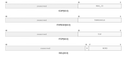
Interrupt-File Control Formats
In the ISEL row, B abbreviates ISEL.BANK.
Each logical processor owns an interrupt file for identities 1 through ICAP.MAX_ID; identity zero is reserved. Each implemented identity has one pending bit and one enable bit. Posting a valid identity sets its pending bit, repeated postings coalesce, and posting zero or an identity above ICAP.MAX_ID has no effect.
An identity is eligible when both bits are set and ITHRESH.THRESHOLD is zero or the identity is numerically less than the threshold. Lower identity numbers have higher priority. ITOP.TOP reads as the lowest eligible identity, or zero when none is eligible. ICAP and ITOP are read-only.
ISEL.WORD selects a 64-identity word and ISEL.BANK selects its view through IDATA. Bank zero reads pending bits and is read-only. Bank one reads zero and writes pending bits with write-one-to-set semantics. Bank two reads zero and clears pending bits with write-one-to-clear semantics. Bank three reads enable bits and replaces the selected enable word on write. A selected word is valid only when it contains at least one implemented nonzero identity. Bits for identity zero or identities above ICAP.MAX_ID are reserved.
Writing ICAP, ITOP, pending bank zero, or an invalid ISEL.WORD raises INVALID_CONTROL_SELECTOR. Nonzero reserved bits in ISEL, ITHRESH, or a writable IDATA bank raise RESERVED_CONTROL_BITS. Validation precedes the write, so a fault changes neither the interrupt file nor its selector. A successful WRCR of ITHRESH or ISEL atomically replaces the selected threshold or selector. A successful WRCR of IDATA atomically applies the selected bank’s write-one-to-set, write-one-to-clear, or enable-word replacement operation.

UCTL Format
UCTL Fields
| Field | Bits | Meaning |
|---|---|---|
| reserved | 63..33 |
must be zero |
V |
32 |
complete user-return bank contains a valid return context |
STATUS |
31..16 |
saved user STATUS image |
FLAGS |
15..0 |
saved user FLAGS image |

PMC Format
E abbreviates PMC.EN in the diagram.
PMC Fields
| Field | Bits | Meaning |
|---|---|---|
| reserved | 63..1 |
must be zero |
EN |
0 |
enable performance-counter increments when set |
WRCR accepts PMC.EN with every reserved bit zero and atomically replaces PMC. Clearing the field freezes the current performance-counter values without clearing them. Selectors 0x0100 through 0x0102 are reserved.